New Edelbrock Performer 455 Buick Heads
by George Nenadovich


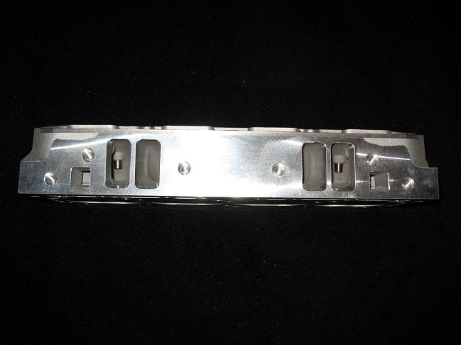
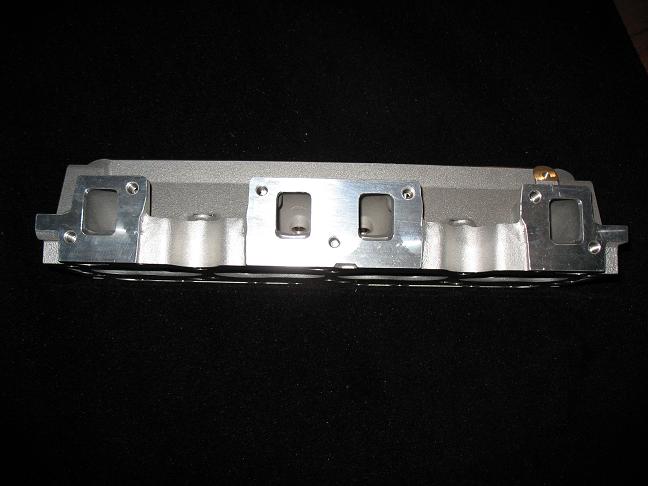
 Pics of bare aluminum Edelbrock heads, part#60039, assembled
versions are #60049
Edelbrock states your compression will increase to 9.2 from
8.5:1 when installing these heads. They recommend 9.650 pushrods, stock
ones will not work. If you have other questions, contact Edelbrock tech
800-416-8628
Flow numbers provided by Mike at TA Performance.
TA converted iron heads to Stage 1, Edelbrock, TA Stage1SE
Intake Flow Numbers CFM
                               Lift   Iron Intake    Edelbrock     TA SE
                              .050”      033.2        033.2        035.0
                              .100”      066.2        068.3        069.9
                              .200”      133.5        130.5        140.4
                              .300”      188.2        194.2        194.2
                              .400”      225.8        250.9        249.1
                              .450”      233.6        269.9        273.1
                              .500”      236.0        278.4        285.3
                              .550”      236.0        280.8        291.9
                              .600”      233.6        283.2        289.7
                              .650”      233.0        282.0        278.6
                              .700”      233.0        280.8        280.8
Exhaust Flow Numbers CFM
                              Lift   Iron Exhaust    Edelbrock     TA SE
                              .050”     028.3          024.4       027.5
                              .100”     056.6          055.0       058.9
                              .200”     109.4          107.0       112.5
                              .300”     132.8          143.7       160.6
                              .400”     146.9          163.8       190.3
                              .450”     156.0          170.0       199.6
                              .500”     159.1          171.6       205.9
                              .550”     159.1          174.7       209.0
                              .600”     159.1          174.7       210.6
                              .650”     162.2          174.7       210.6
                              .700”     162.2          174.7       210.6

Note: Edelbrock heads are the only ones with some clean up work in the bowls. That’s how they came.

 TA heads respond very well to this type of clean up. Iron heads are a little touchier, but will
 respond if done right.
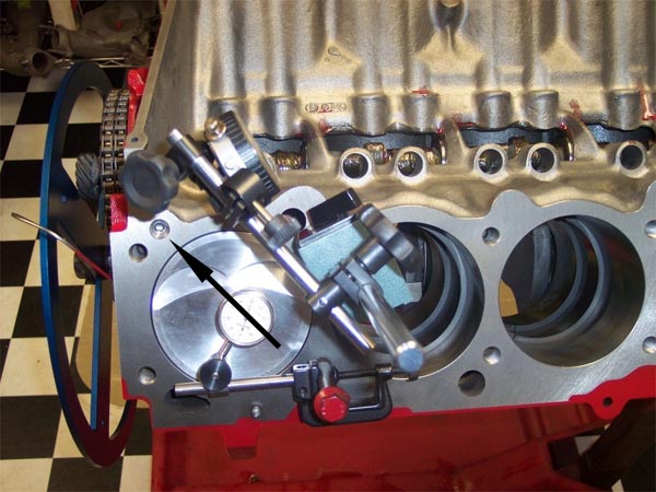
 Notice black arrow pointing to plugged oil feed hole. When changing to Edelbrock heads this needs
to be plugged because there is not complete coverage of this oil feed hole which is a left over
design from 67-69 Buick 400-430 engines which used this hole for oil supply for rocker shaft
oiling. Buick 455 engines from 70-76 use pushrod oil (oil from the lifters) for lubricating the
rocker arms. This is only found on the #1 cylinder.
Flow Numbers as of 7-23-07
by George Nenadovich
Sunnen Pro-Flo 600, Altitude 15 ft, Temp 78 F
Heads were purchased as 60039...unassembled as noted above,
assembled with SS swirl polished valve and very minor clean-up around bowl
area and ports.
| Lift |
Intake CFM |
Exhaust CFM |
| 0.050 |
36 |
26 |
| .100 |
66 |
55 |
| .150 |
96 |
81 |
| .200 |
126 |
103 |
| .250 |
158 |
123 |
| .300 |
192 |
139 |
| .350 |
220 |
152 |
| .400 |
247 |
162 |
| .450 |
266 |
170 |
| .500 |
279 |
175 |
| .550 |
278 |
180 |
| .600 |
276 |
183 |
| .650 |
276 |
184 |
| .700 |
278 |
185 |
- Assembly Notes: When installing the new heads, order Trick
Flow head bolt washers, TFS-51400418
set of 20 runs about $8
- Intake manifold bolts will 3/8-16 by 1 3/4 long. Use washers with
bolts. Torque to 25 ft-lbs after oiling bolt threads and under bolt heads.
- Check guide plates for proper clearance. I used 3/8 pushrods and
due to the stamping process, guide plates were 0.378 which meant an interference
fit. I used as small die grinder to widen the guide plate opening to 0.384
- Tighten upper head bolts to 110 ft-lbs and lower ones to 100 ft-lbs.
Always, lube bolt threads with 30 weight oil and also under bolt heads
to get accurate torque readings.
- Before you order pushrods....order GHP-3520 pushrod length measuring
tool from Gessler Head Porting
and follow the instructions for properly measuring pushrod length.
 Notice two scratches/lines indicated by red arrows. This
is the result of the extra thickness of the cast aluminum valve covers and
the wide roller rockers. This indicates that both rockers arms have to be
shaved on one side. This only happens on the top valve cover bolt holes
on each end of the valve cover.
 Completed shaving each roller rocker arm. The angle of the
material to be removed should match the angle of the thread boss/valve cover
gasket as shown below the rocker arms. In this case....Poston cast aluminum
covers and 1.6 Summit roller rockers, about 3/16 x 3/16" area was removed.
 Slightly different angle showing the ground area.
Notice black arrow pointing to plugged oil feed hole. When changing to Edelbrock heads this needs
 to be plugged because there is not complete coverage of this oil feed hole which is a left over
design from 67-69 Buick 400-430 engines which used this hole for oil supply for rocker shaft
oiling. Buick 455 engines from 70-76 use pushrod oil (oil from the lifters) for lubricating the
 rocker arms. This is only found on the #1 cylinder.